


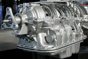
Skip the clutch pedal. Ditch the stick shift. If you drive an automatic, you’ve already accepted that once you slam it into drive, the machine handles the rest. But here is the thing nobody tells you: the automatic transmission and its torque converter achieve the exact same goal as a manual gearbox—transferring engine power to the wheels. They just use wildly different mechanics to get there.
The magic happens inside the casing. Specifically, it starts with the planetary gearsets. These are the unsung heroes of modern automotive engineering.
Зміст
Purpose of an Automatic Transmission
Before diving into the gears, let’s look at the job description. A manual transmission requires the driver to manually select gear ratios. You pull the clutch, move the shifter, release the clutch. It’s physical. It’s involved.
An automatic transmission removes that burden entirely. It uses a combination of hydraulic pressure, electronic controls, and mechanical components to shift gears at the right moment. The driver just accelerates or brakes. The car decides when to change gears.
Why is this amazing? Because it allows for smoother acceleration, better fuel efficiency in stop-and-go traffic, and less wear on the drivetrain compared to a poorly executed manual shift. Plus, it’s just easier to drive.
The Planetary Gearset: The Core Mechanism
The heart of most automatic transmissions is the planetary gearset. It’s a complex arrangement of gears that allows for multiple gear ratios without the need for multiple sets of gears like in a manual transmission.
A planetary gearset consists of three main components:
- Sun Gear: The central gear.
- Planet Gears: Smaller gears that orbit around the sun gear.
- Ring Gear: The outer gear with internal teeth that engages with the planet gears.
By holding one component stationary, driving another, and taking output from the third, you can achieve different gear ratios, overdrive, and even reverse. It’s a clever mechanical puzzle.
How Planetary Gears Work
Imagine the sun gear is connected to the engine. The planet gears mesh with both the sun gear and the ring gear. If you hold the ring gear stationary and spin the sun gear, the planet gears will orbit around it, driving the carrier connected to the output shaft. This creates a reduction in speed and an increase in torque.
Conversely, if you hold the planet carrier stationary and drive the ring gear, the sun gear will spin faster, creating an overdrive ratio. It’s all about which component is held, which is driven, and which provides output.
“The planetary gearset is the key to the whole system. It allows for a compact, efficient, and versatile transmission design.”
Hydraulic and Electronic Controls
The planetary gears themselves are passive. They don’t know when to shift. That’s where the hydraulic and electronic systems come in.
Hydraulic pressure, generated by the transmission fluid and controlled by valve bodies, acts on clutches and bands within the transmission. These clutches and bands hold specific components of the planetary gearset stationary, enabling the desired gear ratio.
Modern automatics use electronic control modules (TCMs) to monitor vehicle speed, engine load, throttle position, and other factors. The TCM determines the optimal shift point and sends signals to solenoids
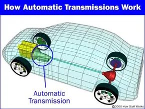

An automatic transmission serves the same basic purpose as a manual transmission. It keeps the engine spinning in its narrow sweet spot while offering a wide range of output speeds. If you leave out the transmission, you’re stuck with one gear ratio. You have to choose a compromise – say an 80 mph gear ratio. If you drive with this setting from a stop, you will crawl without acceleration. Get it up to freeway speeds and the engine would roar as it hit the limits. It would wear out quickly and become almost undriveable.
Gears solve this problem. They multiply the torque and keep the engine in the right range. But towing is a game changer. Towing a heavy load can cause the transmission fluid to boil. Heat destroys seals and lubrication. If you tow, you need a transmission cooler. It’s cheap insurance against the melting your gearbox.
The main difference between manual and automatic systems is the way they change gear ratios. The manual clutch locks and unlocks different gear sets on the output shaft. The automatic uses a fixed set of gears to produce all gear ratios. The magic ingredient? The planetary gearset. It is the core mechanism that makes this possible.
Understanding the Planetary Gearset
Let’s break down how this complex setup works.

Engage the automatic transmission and you’re greeted with some serious chaos. It is very strict. Crowded. Full of hydraulic lines, steel plates and intricate metal work. It has a gear pump that moves the liquid. Equipped with a wet plate switch, it switches on and off. It has a strap that snaps to stop the rotation. But if your heart isn’t beating, it doesn’t mean anything.
The heart is a planetary gearbox.
It’s about the size of a melon. that’s it. It has only one component. However, this single component affects all the ratios produced by the transmission. The rest of the machine, hydraulics, clutches and belts are only support personnel. Their only function is to operate the planetary gear. Tell me what to do.
You may remember this setting from our previous discussion of gear mechanisms. It’s the same principle as an electric screwdriver. There is more than one automatic transmission. You get two complete sets of planetary gears that fold into one compact unit. This is a marvel of technology called compression.
To understand how it works, we need to break it down into DNA. Planetary gear sets consist of three major players:
- Sangia
- Planetary gear and its bracket
–Ring Gear
There’s a list. The trick is that you can use any of the three as input. Both can be used as an output. It doesn’t matter if one of them is in place. Something magical happens in the mix. You can choose who drives, who moves and who stays still. This particular configuration defines the proxy relationships.
Let’s look at the data extracted from a typical transmission.
计算比率
想象一个具有 72 个齿 的特定齿圈。 与它啮合的是具有 30 个齿 的太阳齿轮。
这不仅仅是一个数字。 这是你的底线。
从这两个数字,您可以得出数量惊人的齿轮比。 通过固定不同的部件并向不同的部件输送动力,变速器可以增加扭矩、降低速度,甚至反转方向。 这都是数学,隐藏在钢铁和液压背后。


Lock two of the three main components of a planetary gear – sun, planet carrier, or ring gear – and the entire mechanism locks up. You get a fixed 1:1 connection. No slipping. No delay. Direct mechanical connection only.
Look closely at the ratios. The first is a reduction. The input spins quickly, output crawls. The torque multiplies. The speed decreases. The second ratio flips the script. It’s an overdrive. The output spins faster than the input. Efficiency when driving on the highway depends on this setting. The third option is an additional reduction, but here’s the kicker: the output direction reverses. Reverse gear isn’t magic. It’s just a rearrangement of physics.
There are other relationships that are hidden in mathematics. There are other combinations. But in an automatic transmission, those are the only things that matter. Watch the animation below to see how the gear set creates multiple gear ratios without turning on or off add-ons. Efficiency through simplicity.
Two of these sets of gears in series give you the four forward speeds and one reverse gear that an automatic transmission usually provides. We’ll assemble them in the next section.
Compound Planetary Gearset
This automatic transmission uses a compound planetary gearset. From the outside it looks like a single planetary set Inside, it behaves like two planetary gearsets fused together.
The ring gear acts as a permanent output for the entire transmission. But inside, the complexity doubles. Two sun gears. Two sets of planetary gears. Everything comes together in a precise, synchronized dance.
Let’s break down the components:
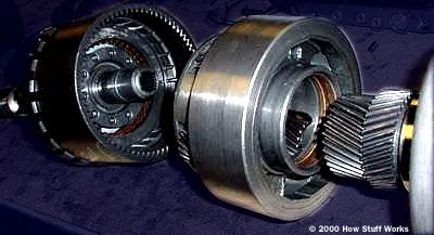

Planet carrier geometry and Ring Gear Engagement
See planet carrier assembly. The arrangement is not symmetrical. Specifically, the planetary gear on the right is lower than its counterpart on the left. This vertical displacement completely changes the flow of power.
The right planet never touches the ring gear. It directly meshes directly with another planet. Only the planet on the left engages the ring gear. This particular configuration determines how the torque is transmitted through the gear train.
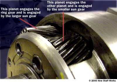

Inside the Planet Carrier
The layout is deceptively simple. You can see how the gears match or not. It’s all about leverage.
Shorter planetary gears have a special function. They only connect with smaller sun gear. That’s it. No distractions. This connection defines the torque transfer for a specific gear ratio.
Longer planets are the heavy lifters. They have two engagement points. The other side bites into a larger sun gear. The other side is connected to the smaller planets. This dual engagement creates a compound path for power.
Longer planets act as mediators and form a bridge between the big sun and the small planets.
Why is this important? Because it allows the transmission to handle different combinations of speed and torque without changing gears. Geometry does the work. The shorter gears rotate freely until they are engaged. Longer gears remain locked to their role.
This design is not only clever. It is efficient. Fewer parts. Less friction. More power to the wheels.
Next? Output shaft. But that’s a story for the next section.
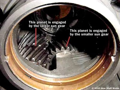

The visual breakdown of a transmission’s internals reveals a complex web of interconnected components. But looking past the animation, the real magic happens in how these parts lock together to change torque and speed. Let’s trace the path through each gear, starting with the low end.
First Gear
Engage first gear, and the smaller sun gear takes the hit. The torque converter’s turbine drives it clockwise. This forces the planet carrier to want to spin counterclockwise. It can’t, though. A one-way clutch holds it firm, allowing rotation in only one direction: clockwise. So, the ring gear takes the load and becomes the output.
The math here is straightforward but deceptive. The small sun gear has 30 teeth. The ring gear has 72. The standard planetary equation gives us:
Ratio = -R/S = – 72/30 = -2.4:1
A negative ratio implies the output spins opposite the input. In reality, the output moves in the same direction as the engine. How? Trickery. This transmission uses two sets of planet gears. The first set engages the second, and that second set turns the ring gear. This double engagement flips the direction back to normal.
Meanwhile, the bigger sun gear spins freely. Its clutch is released, so it spins counterclockwise, opposite to the turbine. It’s just along for the ride.
Second Gear
Second gear is where the engineering gets clever. The transmission doesn’t just swap clutches; it effectively becomes two planetary sets married at the hip, sharing a common planet carrier.
Here’s the setup. The first stage treats the larger sun gear as the ring gear. So, your three players are:
1. Input: The small sun gear.
2. Fixed: The large sun gear (held by a band).
3. Output: The planet carrier.
Apply the formula for a fixed ring gear:
1 + R/S = 1 + 36/30 = 2.2:1
The planet carrier turns 2.2 times for every single turn of the small sun gear. But we’re not done. That planet carrier is now the input for the second stage.
In the second stage:
* Input: The planet carrier (from the first stage).
* Fixed: The larger sun gear (still held stationary).
* Output: The main ring gear.
The ratio for this stage?
1 / (1 + S/R) = 1 / (1 + 36/72) = 0.67:1
Multiply the two stages together: 2.2 times 0.67. You get a final reduction of 1.47:1. It’s a compound gearset, but the result is a smooth, usable gearing for acceleration without stalling the engine.
Third Gear
Most automatics drop into a 1:1 ratio for third gear. Direct drive. No multiplication, no reduction. Just a direct path from input to output.
To get this, you only need to lock any two of the three planetary components together. In this specific design, the move is simple. Engage the clutches that bind both sun gears directly to the turbine.
If both sun gears spin in the exact same direction, the planet gears have no choice. They can’t spin against each other. They lock up. This locks the ring gear to the planets. Everything spins as one solid unit. 1:1. Simple. Efficient.
Overdrive
Overdrive means the output spins faster than the input. It’s a speed increase, the antithesis of torque multiplication.
This transmission pulls double duty when overdrive engages. It combines an overdrive gear ratio with a lockup torque converter. Remember the lockup? It bypasses the fluid coupling, sending engine power straight to the transmission for better efficiency.
When you hit overdrive:
* A shaft attached to the torque converter housing connects via clutch to the planet carrier.
* The small sun gear freewheels.
* The larger sun gear is held by the overdrive band.
* Nothing connects to the turbine. The only input comes from the converter housing itself.
Look at the chart with the planet carrier as input, the sun gear fixed, and the ring gear as output:
Ratio = 1 / (1 + S/R) = 1 / ( 1 + 36/72) = 0.67:1
The output spins once for every 0.67 rotations of the engine. Do the math. If the engine is idling at 2000 RPM, the output shaft is spinning at 3000 RPM.
This is why you can cruise on the freeway at 70 mph while the tachometer sits comfortably low. The engine isn’t working hard. The transmission is gearing it up.
Reverse Gear
Reverse looks a lot like first gear. Same setup, different driver. Instead of the small sun gear being driven by the turbine, the big sun gear takes the load. The small sun gear freewheels in the opposite direction.
The planet carrier is pinned to the housing by the reverse band. It can’t move.
Apply the equations from earlier. The result is a ratio slightly lower than first gear. The car moves backward with a bit less torque multiplication, but enough to get you out of a tight spot.
Gear Ratios
That’s the cycle. Four forward gears and one reverse. The transmission shifts through them by holding specific elements stationary and driving others, using the planetary gearset’s versatility to manage power delivery.
| Gear | Input | Fixed Element | Output | Ratio |
|---|---|---|---|---|
| 1st | Small Sun Gear | Planet Carrier (One-Way Clutch) | Ring Gear | 2.4:1 |
| 2nd | Small Sun Gear | Large Sun Gear (Band) | Ring Gear | 1.47:1 |
| 3rd | Both Sun Gears (to Turbine) | N/A | Everything Spins Together | 1:1 |
| OD | Converter Housing | Large Sun Gear (Band) | Ring Gear | 0.67:1 |
| Rev | Large Sun Gear | Planet Carrier (Band) | Ring Gear | Slightly < 2.4:1 |
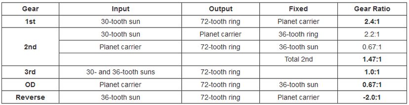

You’ve probably wondered how to connect and disconnect different inputs. This is done using clutches and bands inside the transmission. In the next section we will see how these work.
Clutches and bands in the automatic transmission
In the last section we discussed how the transmission creates the individual gear ratios. For example, when we talked about Overdrive, we said:
In this transmission, when the overdrive is engaged, the shaft attached to the torque converter housing (which is bolted to the engine flywheel) is connected to the planetary carrier via a clutch. The small sun gear rotates freely and the larger sun gear is held in place by the overdrive band. Nothing is connected to the turbine; The only input comes from the converter housing.
In order to get the transmission up and running, many things have to be connected and separated with clutches and bands. The planet carrier is connected to the torque converter housing via a clutch. The small sun is separated from the turbine by a clutch so that it can run freely. The large sun gear is attached to the housing with a band so it cannot rotate. Each gear shift triggers a series of such events that engage and disengage various clutches and bands. Let’s look at the band.
Bands
This transmission has two bands. Transmission bands are literally steel bands that wrap around the transmission parts and connect to the housing. They are used with hydraulic cylinders in the gearbox housing.
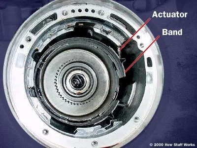
Transmission Band Mechanics
Remove the gear sets and you are left with the raw innards of the transmission. See the case. One of these critical hold-down bands is visible. It’s not just decoration. It’s a muscle.
The metal rod is connected directly to the piston. Push the rod. The piston moves. The band gets tighter. This simple chain reaction prevents certain rodrels from spinning. Do you want a reverse gear? You apply pressure. The band clamps down. The car is going backwards. Want a low gear? Same band. Different timing.
The band acts as a brake and secures part of the transmission to the case.
There are no computers here. Just hydraulics and steel. The rod takes hydraulic pressure and converts it into mechanical force. The piston does the heavy lifting. The band does the holding. What if the rod gets stuck? What if the piston leaks? You will lose that gear. Or that reverse. The whole thing grinds to a halt.
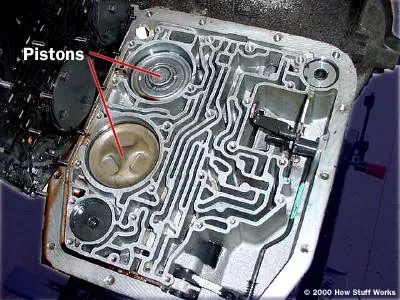
Hydraulic pressure is the muscle behind the shift. It is fed into the cylinder through a special set of valves and forces the pistons to push hard against the bands. This action lockes part of the transmission to the housing, effectively changing the way power flows through the transmission. It is a mechanical handshake that takes place with flowing force.
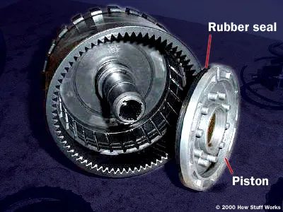
The clutches tell a different story. They are more complex than bands. This particular transmission uses four different clutch packs to control the shifting process. Each is activated by pressurized hydraulic fluid that flows to a piston located directly in the clutch assembly.
When this pressure drops, the system must have a way to release itself. This is where springs come into play. They ensure that the clutch releases cleanly when the hydraulic pressure drops. If you look at the piston and the clutch drum surrounding it, you will see a rubber seal on the surface of the piston. It’s a small part, but it’s crucial. This exact seal is replaced when your transmission goes to the workshop for service. Without it, pressure losses and shifts slip.
Why rubber seals are important in rebuilds
You can think of a rubber gasket as just a gasket. In an automatic transmission, it is a pressure keeper. When a transmission starts shaking or slipping, the internal seals are often the first suspect. They harden over time and lose their ability to maintain the hydraulic pressure needed to lock the clutches.
Replacing isn’t just about fixing a leak. It’s about restoring the exact friction surface that the clutch plates must engage with. When you disassemble a transmission for a rebuild, you don’t just install new friction plates. You’re refreshing the integrity of the hydraulic circuit. The piston seal ensures that the force from the valve body actually reaches the clutch pack instead of escaping past the piston wall.
The hidden cost of wear and tear
The simplicity of a piston moving in a drum is easy to overlook. But this shiftment is everything. A broken seal, a worn spring and the whole chain of events collapses. The bands can still lock, but the clutches won’t. Power gets lost in the slip.
That’s why rebuild is so labor-intensive. It’s not just about cleaning parts. It’s about replacing every part that has gone through thousands of cycles of heat, pressure and friction. The rubber seal on this piston is just one piece of a much bigger puzzle. If you skip it, the transmission will fail again. Respect it and it can last another hundred thousand miles. Or maybe not. The road is bumpy for these things.
Clutch package: friction meets steel
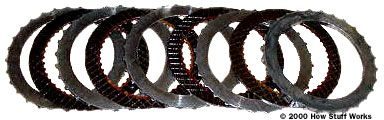
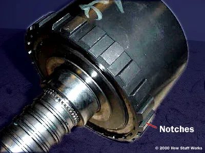
The clutch package consists of alternating friction material layers and steel plates. Inside Friction plates are interlocked to lock into one of the gears. From the outside, the steel plates are locked into the switch housing. This sandwich type arrangement transfers power through friction.
These components are victims. They wear out with use. If you are rebuilding the transmission, replace it. The new plates guarantee perfect support and longevity. Ignoring this step will lead to slippage and possible failure.

Clutch pressure is no accident. It moves through internal channels built directly into the transmission shafts. The hydraulic system acts as the brain, deciding in a fraction of a second exactly which clutches and bands need to be activated to keep the flow of power steady.
The logic behind the parking position
Moving to the park sounds trivial. All you have to do is lock the transmission so the wheels don’t spin. But the technical requirements behind this simple lever movement are surprisingly complex.
Consider physics. First, the system must disengage or hold when the car is on a hill. The entire weight of the vehicle presses on the locking mechanism. It can’t slip.
Second is the alignment problem. The shift lever rarely lines up with the gear selector perfectly every time. Even if there are small deviations in the inputs, the mechanism must engage reliably.
Third, the lever must remain in place after locking. Something has to stop it from jumping up and accidentally disengaging. Vibration from the road or a bumped console must not unlock the car.
A mechanism that adapts to all these constraints is surprisingly elegant. Before we get into how it actually works, it’s helpful to understand the individual components involved.
How the parking brake stays on track
The parking brake doesn’t just pull the cables; it works directly in the gearbox. It engages the teeth of the output shaft to prevent the vehicle from rolling. This is a special part of the transmission that connects to the drive shaft. If the parking brake locks, this part cannot rotate. And if this part can’t rotate, the car can’t move. It’s a mechanical lock. Simple. Effective. Stopping a car from rolling down a hill requires no electronics.
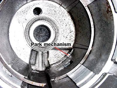
How conical parking mechanisms make it easier to climb slopes
Look closely at the parking brake assembly in the differential case. You’ll notice the parking lock – a small metal tab that locks the gears into place. It’s not just a flat plate. It has tapered sides that are slightly angled to guide it back and forth.
This design solves a common problem. Parking on a steep slope puts a huge strain on the transmission. The weight of the car wants to roll, but the brakes hold it in place. This creates a binding force. If the latch were flat and rigid, it would fit snugly against the gear teeth. Freeing it later? This often requires raising the rear wheels or putting a lot of pressure on the drive shaft.
The taper changes the physics. When you release the brake, the inclined surface acts as a ramp. Gravity and the vehicle’s own weight help push the mechanism out of its locked position. The force from the position of the vehicle actually helps release the lock. No more struggling with a stuck emergency brake. It’s a simple geometric trick that makes it easier on your shifter and your patience.
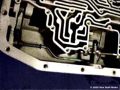
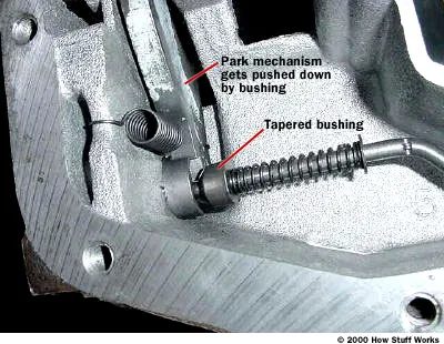

The physical connection between your shifter and the transmission is a simple but important link. It is connected to a cable that converts your hand movements into mechanical movements. When you push the lever into park, that rod shoves a spring against the small, conical sleeve.
Here’s the catch: the mechanism only locks when it lines up with the notch on the output gear. If the car is stopped on a slight slope or the gears are only slightly tilted, the tapered bushing will hit the “high spot” of the gear. The spring presses, but the lever does not catch. This is why your car may creep forward or backward a few inches after you put it in park and release the brake. It’s not a malfunction. The vehicle should roll just enough so that the teeth are aligned and the parking pawl will eventually fall into the notch.
Once aligned, this bushing holds the lever in place. It keeps the transmission in park even if you’re sitting on a steep hill. Without this mechanical stop, gravity would knock the car out of gear.
Automatic transmission: hydraulics, pumps and governor
Hydraulics
The automatic transmission does a lot more than you think. It’s not just a shifter; It is a complex hydraulic computer that controls the power delivery. Consider these behaviors you experience daily:
- Thanks to the four-speed Overdrive transmission, the system automatically selects a gear based on speed and throttle.
- Gentle acceleration triggers shifts at lower speeds. Floor it, the transmission will hold the gears longer.
- Pressing the gas pedal forces an immediate downshift to the next lower gear.
- Moving the selector lever to a lower gear (e.g. 2 or 3) only triggers a downshift if the vehicle’s speed allows it. If you drive too fast for this gear, the transmission will wait. It won’t force a downshift until the car naturally slows down.
- If you lock the shifter in second gear, the transmission stays in second gear. It will not upshift or downshift unless you move the lever.
This logic is controlled by the hydraulic control system. You’ve probably seen the metal block that directs fluid to all of these components. It’s basically the brains of the automatic transmission. Ducts molded directly into the metal housing are much more efficient than using external tubing. Without these internal channels, the transmission would be a tangled mess of rubber tubes.
We need to look at the key components of this hydraulic system to understand how they work together.
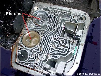
Hydraulic core: Gear pumps
Look under the transmission housing and you will find the automatic transmission gear pump. It is a mechanical motor behind the hydraulic pressure, usually mounted directly on the deck.
Its job is straightforward but relentless. It draws fluid from the sump – the reservoir at the bottom – and pushes it into the veins of the system. This pressurized fluid won’t just sit there. It goes to the torque converter, lubricates and activates the engine’s power. It also hits the cooler and prevents the transmission from melting under load.
Without this constant pull, the whole system collapses. The pump doesn’t care if you’re in park or in third gear. It runs whenever the engine is running. That’s why fluid levels are so important. Low fluid means the pump is sucking in air. The air compresses. Pressure drops. Shifts become sloppy, then hard and finally non-existent.
It’s a simple design. The gears connect to each other. The liquid is trapped and pushed. But it is also the most vulnerable part. When the seal fails or the gears wear out, it’s not just pressure that’s lost. You lose control. And with an automatic transmission, that means you’re stuck in neutral, hoping a tow truck finds you before your battery dies.
Some modern designs use variable displacement pumps to save fuel. They reduce flow when high pressure is not required. But the basic principle remains the same. Pull. Press. Circulate. Fail, and the transmission is no longer a transfer. It becomes a paperweight.
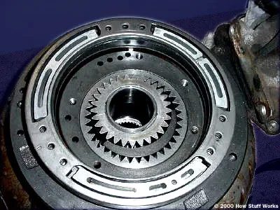
The pump’s internal gear is bolted directly to the torque converter housing so that it rotates at engine speed. As the gears spin, they collect fluid on one side of the crescent-shaped housing and force it into the hydraulic system on the other side. The outer gear, driven by the inner one, helps move this flow, but the actual task of measuring the vehicle’s speed is left to another component.
The role of the governor
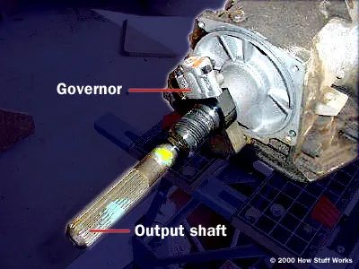
The automatic transmission governor is a mechanical valve that is responsible for indicating the current speed of the transmission. It is mounted on the output shaft and spins faster as the car accelerates. A spring-loaded valve inside reacts to this rotation. The faster the shaft rotates, the stronger the centrifugal force presses against the spring and opens the valve further. Fluid from the pump flows through the output shaft to reach this valve.
This setup creates a direct relationship between speed and pressure. Higher vehicle speed causes the governor to spin faster, opening the valve more and letting more fluid pressure through. This pressure signal determines when the transmission shifts gears.
The governor converts the mechanical speed into hydraulic pressure and gives the transmission the information it needs to shift automatically.
This mechanism is purely mechanical. No electronics involved. Only springs, valves and fluid pressure reacting to centrifugal force. It’s an elegant, if somewhat outdated, solution to the problem of knowing how fast a car is moving. Modern transmissions have largely replaced this with electronic sensors, but the principle is still a key concept in automatic transmission design. Why did they change it? Mainly for precision and because computers can read multiple inputs at once, not just output shaft rotation. But for those who keep older cars running, understanding this governor is key to diagnosing shift issues. If the shifts come hard or late, the governor may be to blame. Or maybe the valve body. Or the fluid itself. It’s rarely just one thing. But knowing how the governor works helps narrow your search.

How automatic transmissions sense engine stress
Shift quality is not magic. It is a hydraulic system that responds to physics. The transmission needs to know one thing: how hard the engine is working. Two main methods handle this data.
Some older or simpler models use a direct throttle connected to the gas pedal by a cable. Step on the pedal. The cable pulls. The pressure is building. Simply. Linear.
Other systems use a vacuum modulator. This membrane detects manifold vacuum. Under heavy loads, the vacuum drops. The modulator converts this change into hydraulic pressure and pushes against the throttle. Either way, the goal is the same. Tell the transmission when to shift based on throttle position.
Role of manual valve
The Manual Valve is the connection to your shifter. It is purely mechanical. Move the lever to position “D”, “3” or “L” and the valve will physically control the fluid. It blocks certain circuits. Select third gear? The overdrive circuit is broken. No overdrive. Choose low? High gears remain passive. It’s a hard limit set by the driver.
Shift Valves: The Decision Makers
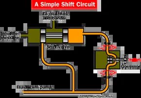
Inside the valve body, the switching valves do the actual work. They direct the fluid to the clutches and bands. Each pair of gears has its own valve. The 1-2 gear valve controls the shift from first gear to second gear. 2-3 takes the next step.
These valves are in a tug-of-war. On the other side, the Governor fluid pushes in one direction. The governor rotates with the output shaft. Speed creates pressure. On the other hand, the throttle valve pushes back. The load creates resistance.
The pump produces both pressures. The shift valve only moves when the governor’s pressure exceeds the throttle resistance.
Why shift points change
Acceleration is important.
Drive carefully. Throttle pressure is low. The governor’s pressure, which builds quickly, wins early. The shift takes place at a lower speed. Smooth.
Step on the pedal. Throttle pressure peaks. The governor has to work much harder to move the valve. The car must go faster before switching. You hold the gear longer. You get more power. This is why shifts feel aggressive at full throttle – they’re delayed by design.
Each valve responds to a specific pressure range. As the speed increases, the 2-3 valve takes over. The 1-2 valve closes. The 3-4 valve (or overdrive) is waiting its turn. It is a series of hydraulic decisions.
The Electronic Shift
This mechanical dance works well. It is predictable. But it has limits. Vacuum varies with altitude. Cables stretch. Modulators leak. The system relies on imperfect sensors.
Enter the electronics. Modern transmissions don’t rely on cables or a vacuum. They trust data.
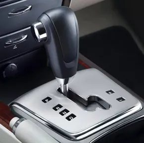

Modern automatics are a hybrid of analog guts and digital brains. You might see “electronically controlled” on the spec sheet, but don’t think the hydraulics are gone. They’re still there. The clutches and bands are still actuated by fluid pressure. The difference? Electric solenoids now manage the hydraulic circuits. This swap simplifies the plumbing inside the transmission case and unlocks control schemes that a purely mechanical valve body simply can’t handle.
While older systems relied on basic vacuum and mechanical linkages, the new generation monitors far more data. Yes, it still watches vehicle speed and throttle position. But now it also tracks engine RPM, brake pedal engagement, and can even interface with the anti-lock braking system. This data feeds into sophisticated algorithms. Many use fuzzy logic—a programming approach that mimics human reasoning rather than relying on rigid binary rules—to make shifting decisions.
Smarter Shifting for Safety and Efficiency
This intelligence allows the transmission to react to driving conditions in ways that feel almost instinctive. It’s not just about getting from A to B. It’s about preserving hardware and managing traction.
- Downhill grade compensation: The system detects steep descents and downshifts automatically. This uses engine braking to maintain speed, reducing wear on the friction brakes.
- Slippery surface management: If sensors detect wheel slip during braking, the transmission may upshift. This reduces engine braking torque, helping to prevent loss of control.
- Cornering inhibition: On winding roads, the transmission can inhibit an upshift into overdrive. This keeps the engine in its power band, ready to accelerate out of a turn without a laggy downshift.
Consider the winding mountain road scenario. You’re climbing a switchback. The straight sections trigger a shift into second gear for torque. You hit a curve. You lift off the throttle. A basic automatic might interpret this as a cue to upshift to third or even overdrive. Then, as you hit the gas exiting the curve, it has to downshift again. It’s jerky. It’s inefficient. In a manual car, you’d just hold the gear.
Advanced electronic units can learn from this pattern. After navigating a few curves without shifting, the controller recognizes the context. It suppresses the upshift logic, keeping you in the optimal gear for acceleration until the road straightens out again. It’s subtle, but the difference in driveability is noticeable.
Automatic Transmission FAQ
What is the main difference between an automatic and a manual transmission?
Two key distinctions. First, there is no clutch pedal. Second, there is no manual gear lever for selecting ratios. Once placed in “Drive,” the system manages all gear changes autonomously.
What is the primary function of an automatic transmission?
Its job is to keep the engine operating within its most efficient RPM range while providing a wide variety of output speeds to the wheels.
When did automatic transmissions become the standard in the U.S.?
According to Sixt, automatics became the dominant choice in the U.S. market in the late 1980s.
How does an automatic transmission actually work?
Driving.ca notes that these systems use sensors to determine shift timing and execute gear changes using internal oil pressure.
What components are inside an automatic transmission?
The internal assembly typically includes a planetary gearset, a set of holding bands, three wet-plate clutches, a hydraulic control system, and a large gear pump.

